Upgrade parts
About Full Option
Home
Project vehicles
Suspension
Rear

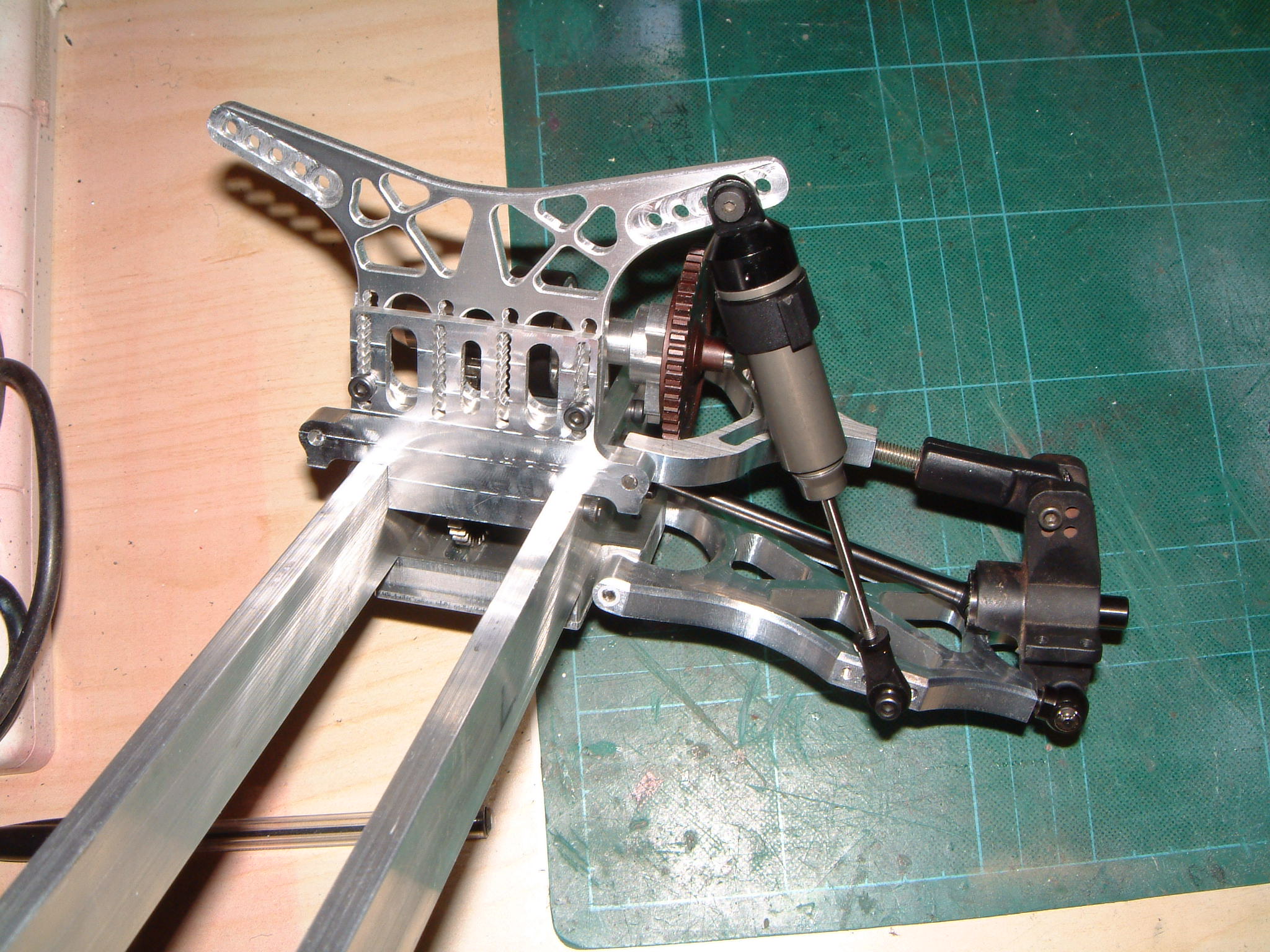
The suspension is definitely my favourite area when building a car.  I played around for many hours trying to come up with the best way to arrange the suspension, especially at the rear.  Real class-1 buggies almost all run trailing arm rear suspension, which is exceptionally strong.  The major problem I kept finding, no matter how I configured a trailing arm design, was the change in length of the driveshafts.  I could never get it small enough to be able to use commercial shafts, so I would have had to make my own telescopic shafts and diff outdrives.  All possible, but not without a lot of effort on a very vulnerable part.  I viewed this as too much of a compromise so decided on double wishbone suspension.  The challenge now would be to integrate this while still retaining enough of a scale look as it is a fundamental difference between this car and the real thing.
Designing the wheel tragectories for the rear was not all that difficult, after all these wheels don't have to steer.  The problem was placing the mount points with so many other parts getting in the way.  Lower wishbones were no problem and I had these made pretty quickly in super tough 8mm 6082.  I built 3 degrees of toe-in into them.  The top links have to be wrapped around the spur gear on one side and the brake caliper, actuation arm and engine crankcase on the other.  This particular part was re-made 3 times until sufficient clearance was achieved at the bottom-out and top-out positions in the suspension travel.  I'd like to do the next project vehicle in full 3D CAD with motion simulation which would really help with this kind of problem.  In the end I get about 2.5" of wheel travel out of this rear end with many parts having sub-millimetre clearances.

Rear springing is another area where this buggy departs from 4WD machines.  Because of the amount of weight placed behind the rear axle, no commercially available RC springs are stiff enough for the rear shocks.  To achieve the correct ride height with the stiffest 1/8 scale springs I have requires over 1 inch of preload spacers, and of course the spring rate itself is still far too low.  Buying engineering springs of the correct rate is an option, but if multiple rates are required for tuning purposes this can be pretty expensive.  I decided to run a separate auxiliary spring in parallel with the standard 1/8 spring on the coilover unit.  The aux spring would therefore not need to be very stiff, and changing it's preload would alter the ride height of the rear of the buggy without having to touch the main shock.  The whole thing could be wrapped up in a 'piggyback' style unit which would look a lot like the external reservoirs and bypass units the real buggies have.
TM
Checking the assembly of the left rear suspension.  Notice the proximity of the spur gear to the upper wishbone.  The right-rear wishbone (not shown) was a completely different shape by the final iteration.
Making sure everything articulates freely.  I used a shock set for the GS Storm Pro, which are really nicely made.  The major suspension arms pivot on solid PTFE bushings which can easily be replaced when worn out.  To change the ride height, spring spacers can be used as normal, or the whole tower can slide up and down on its mountings.
Continue
Back to project index
Full travel demonstration.  Like most RC buggies, the chassis hits the floor before the shocks bottom out, preventing damage to the shocks.  The underside of the chassis is more than man enough to take this beating.
I modelled many of the heavily load-bearing components in 3D CAD and performed finite element stress analysis on them.  This temporary shock tower doesn't look likely to hold up under 6ft plus jump landings!  The final part will be a 7075 item with carbon fibre inserts which will have a massive impact on the strength.
Front

I copied much of the geometry from the Losi XXX and AE B4 buggies.  Obviously it is scaled up both in size and strength (considerably).  I'm using Hobao Hyper 7 shocks which are amazing.  After 6 years of hard use and no maintenance in a Traxxas Stampede I pulled these shocks apart and poured out a full cylinder of water clear oil from each shock!
Springing is not a problem with the lightweight front end, I've set it up initially with very light damping and fairly soft springs.  I figured I'd need a fair bit of weight transfer to the front to get some steering bite with no 4WD to help.  Plus it should emulate the massive body roll and pitch of the class-1 beasts.  It could have a ton more travel than it currently does, with no drive shafts to worry about.  I wanted to keep a fair balance in travel between front and rear though.
Having no drive shafts up front introduces another plus that is not obvious.  You can mount the shock right in the middle of the arm, rather than on the leading or trailing edge.  This means that no torque is applied to the suspension bushings as the shock compresses.  This reduces friction and wear, and keeps the travel smooth all the way to bottom-out.  Unlike 4WD buggies which are basically twisting the suspension arm more and more as you go up the travel, so they get less and less supple the harder you hit them.

Kick-up is as electric 2WD buggies - 25 degrees.  There are a couple of neat feaures I incorporated that I've used before with success, like solid PTFE bushes for the main wishbones.  This gives a 100% slop-free suspension with no perceivable drag.  And the bushes are much easier to replace  than a complex aluminium suspension arm when they wear out.  The outboard hinge pins are solid tungsten carbide (precision ground rod).  Super hard wearing, but quite brittle as anyone who does machining with carbide tools will know.  In an impact the stock plastic c-hubs should survive and flex, hopefully breaking the brittle pin which is easy to replace.