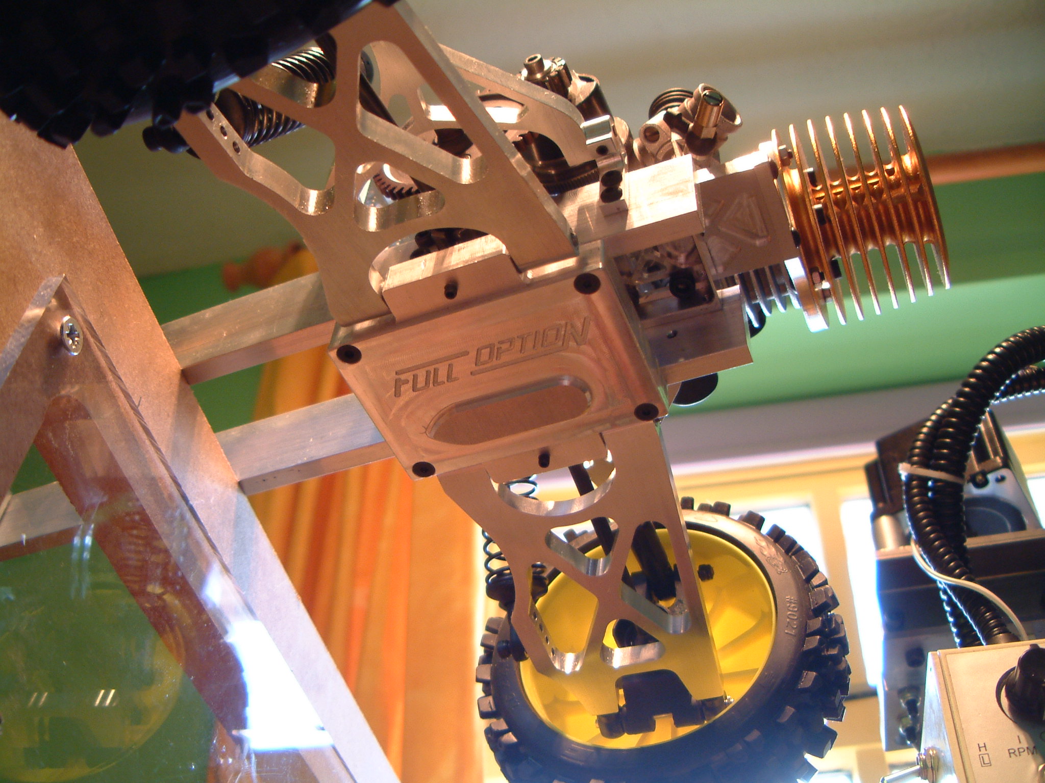
Now I had a chassis plan roughly laid out in CAD, I spaced the twin rails just wide enough to accommodate a commercially available differential between them. Unlike all current 1/8 buggies, the engine is mounted transversely. This means I can use a straight-cut spur gear on my diff, which naturally leads to using a centre diff out of a 4WD buggy. Again my wrecked Kyosho 7.5 provided the hardware although I will upgrade this to top line stuff at some point. Also unlike other buggies, the engine is mounted flat which has a huge beneficial impact on the CG. The downside to this layout is an exceptionally tight space in which must be fitted the engine, two discs, calipers, diff, and all the required reduction gears.
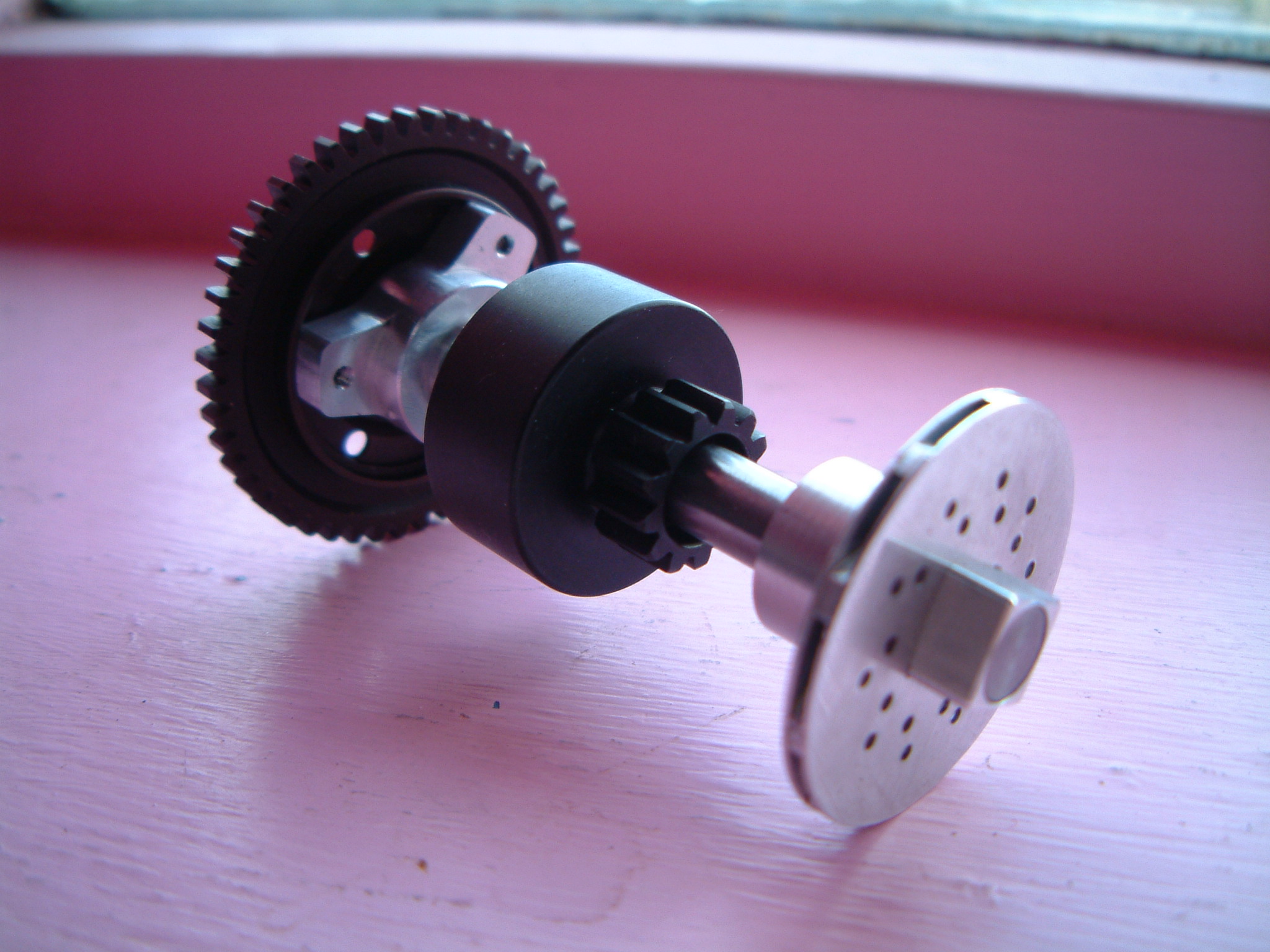
The final drive ratio is basically the same as on any other buggy. You can fine tune it as normal by using different sized pinions. The rest of the transmission is based around a precision ground 8mm silver steel layshaft. This carries the primary spur gear, secondary pinion and two brake discs. The secondary pinion is actually fitted to a redundant clutch bell - this is only because it was the easiest way to get the correct size gear onto the shaft. At this point I am considering gears to be another of the expendable items I will avoid making.
Once the layshaft was mounted onto the chassis it became clear just how little space there was to work with. Unfortunately my experimental ventilated brake discs were far too big at 35mm diameter - see the brakes page for more info. I wasn't making it any easier by making the chassis rails so tightly spaced, but this was for good reason. Any wider and the mounting points for the suspension would be wider too, which would require shorter wishbones to give the standard 1/8 scale car track width. That's not good because I wanted to have long suspension travel.
The final touch to the transmission is the lower gearbox case. This acts as a hanger for the rear suspension and there's a protective cover to stop getting into the diff area.